3.3 - WEIRS IN THE SPILLWAY
As shown in the previous paragraph, before reaching the drop, the discharge flow generally falls in the subcritical range, right on the drop the flow is critical, and beyond the drop it becomes supercritical (see figure 3.10). Here, water flowing in the supercritical range erodes the streambed, downstream the weir, due to the progressive energy dissipation that follows the flow discharge.
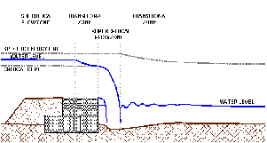
Fig. 3.10 - Water flowing on a weir
In this paragraph, weirs are firstly classified according to shape (U.S. Department of the Interior Bureau of Reclamation. 1987, Maccaferri 1990a ). Then, weirs will be classified according to their hydraulic function with reference to the problem of energy dissipation. Hydraulic computations will be presented in the third part of this paragraph with regard to vertical weirs. In fact, a vertical downstream side is the most common in small hydraulic works. Finally, the stability computation for gabions structures will be explained in the fourth part of the paragraph.
3.3.1 - Shape of the weir's downstream side
Weirs can be classified, according to the shape of their downstream side, into three classes (as shown in fig 3.11):
-vertical
-stepped
-battered
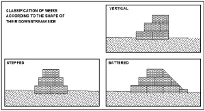
Fig. 3.11 - Weir shapes
The shape of the downstream side of a weir must be chosen according to several factors, such as:
-drop height,
-hydraulic charge,
-characteristics of the materials employed in gabions building,
-characteristics of local natural soils,
-weir class according to the first classification mentioned above (in respect to the presence of a stilling basin).
There are no general rules for the choice of a particular shape. However if the drop's height does not exceed 3-5 m, the vertical shape is always the most appropriate.
If the drop height is higher than 3-5 m, the weir must be designed with a stepped shape, which, however, can be used only if the specific flow does not exceed 3 m3/s/m.. Otherwise the turbulence and the shock provoked by water dropping on the step can bring about severe breakage in the gabions. In Cemagref's interesting synthesis of experimental observations on stepped gabions weirs, it is argued that if the drop is higher than 3¸5 m, and the specific flow does not exceed 1 m3/s/m, the battered shape would also be suitable (Peyras , Royet , Degoutte. 1991).
Step- and batter- shaped weirs are not well fitted to natural streams with a significant solid transportation, especially when gravel and rubber are transported by the flow. In fact, the continuous dropping and sliding of particles on and through gabions can provoke net tears.
In chapter IV, a number of techniques that can be adopted to face gabions failure will be illustrated for each kind of weir shape.
The weir's upstream side should always be stepped in order to facilitate the bonding between gabions and earthfill, which functions so as to make the weir impervious. Moreover, earthfill's weight on the weir steps adds stability to the structure, contributing to prevent sliding and overturning events (see paragraph 3.3.4).
3.3.2 - Type of weir
Sometimes, natural flow conditions downstream the structure, can provoke a concentration of energy dissipation in a circumscribed zone. Otherwise, a structure on purpose (stilling basin) will have to be realised downstream the weir.
With reference to the problem of energy dissipation downstream the structure, weirs can be classified in four categories (U.S. Department of the Interior Bureau of Reclamation. 1987, Maccaferri 1990a ) (see figure 3.12).
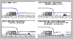
Fig. 3.12 - Type of weirs (case A, B, C and D)
-simple (A),
-with counterweir, unlined stilling basin (B),
-with counterweir, lined stilling basin (C),
-with counterweir, stilling basin located below the natural river bed (D).
The methods used to ascertain that the energy dissipation is concentrated immediately downstream the weir will be illustrated in paragraph 3.3.3.
3.3.3 - Hydraulic design
The procedures explained below are primarily related to the hydraulic design of weirs with a vertical downstream side. Vertical weirs are the simplest to design and to build, accounting for their widespread use as small hydraulic works, especially in developing countries. Hydraulic dimensioning procedures for stepped and battered weirs will be only briefly mentioned. It should be noted, however, that some weirs with a stepped downstream side, can be dealt with in the same way as vertical weirs, with respect to hydraulic computations, if the downstream side slope is so important that water jumping from the weir crest does not flow on the steps but falls straight upon the weir toe, downstream.
At the initial stages of weir design, the only known characteristic is its height. The weir's height depends upon the difference between design slope and original slope. In order to limit erosion problems, if the weir is expected to be taller than 2¸4 meters it could result useful to build more than one weir, depending on the natural soils characteristics and on the quality of construction materials (see figure 3.13).

Fig. 3.13 - Channel longitudinal section with weirs
The flow-depth relationship in Chezy's formula

allows the calculation of the water's depth atop the weir (h), provided that design flow (Q), discharge coefficient (m) and weir's width (b) are known.
Discharge coefficient values are tabulated according to water charge (h) and weir crest length (see figures 3.14 and 3.15 ) (Cremonese. 1996).
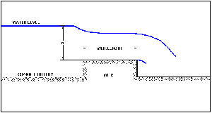
Fig. 3.14 - Weir schematisation
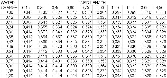
Fig. 3.15 - Discharge coefficient values
The discharge coefficient range is wide: its values generally vary between 0.3 and 0.4. Choosing the right value for the discharge coefficient is not easy, as it also depends on the crest's roughness conditions, which may vary during runoff (e.g. if shrubs carried by the flow get trapped in the gabions net). It should be noticed that the values of the discharge coefficient are not available for submerged weirs (e.g. downstream water level higher than the weir's crest).
The engineer designing a weir, should chose a limit value for the discharge coefficient in order to maximise the water depth with a fixed flow design. For example, for a gabions weir completely filled with sediments upstream, and with a water depth between 1 and 2 metres, a prudential discharge coefficient value would be 0.35.
The maximum water depth should be kept within a limited range of values, with a peak value of 2¸3 metres, modifying weir's width accordingly, if necessary. The problems that could arise in a weir when the water charge exceeds 2 metres are discussed in chapter VII. This chapter will introduce building solutions that allow the weir to support greater water charges (i.e. reinforced concrete lining of the stilling basin).
After having fixed the weir's main dimensions (e.g. height, width, water charge) it is necessary to verify what happens downstream the structure. As we have seen, the engineer must ensure that the energy dissipation is concentrated immediately downstream the structure. This condition is satisfied when a subcritical flow, with particular characteristics, takes place downstream the structure.
It is also important to make sure that, between this subcritical flow and the flow coming out from the weir (generally supercritical) the conditions for the installation of a hydraulic jump are fulfilled.
Several methods can be adopted for proceeding to this verification. The choice of the most appropriate method depends on the weir type, selected according to the classification suggested in paragraph 3.3.2. These methods and the procedure for dimensioning a stilling basin are explained below (U.S. Department of the Interior Bureau of Reclamation. 1987, Maccaferri 1990a ).
Simple weir
For a very small weir with limited specific flow and energy dissipation, the gabions structure can be realised omitting the stilling basin. This solution is likely to be chosen especially if the streambed material is resistant. Otherwise dropping water could dig a hole downstream the weir. In this case, it will be necessary to calculate hole depth and the distance between weir structure and hole.
With reference to figure 3.16, considering that the flow, on the weir, falls in the critical range, the distance X can be computed through the following rough relation:
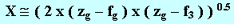
Scour depth can be computed with Schoklitsch's relation expressed, always with respect to figure 3.16, by:

where z3, fb, z0 are expressed in meters, q, expressed in m3/s, represents the specific flow, and dt is the sieve diameter through which passes the 90% of streambed material. For safety reasons, the weir's foundation level should be lower than the hole's minimum level.
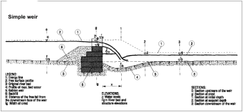
Fig. 3.16 - Simple weir
Weir with counterweir and unlined stilling basin
A counterweir can be built in order to reduce the erosion phenomenon caused by energy dissipation downstream the weir. This will cause the water level downstream the weir to increase, and the scour depth will be reduced.
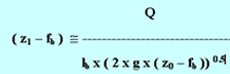
With regard to the weir, the counterweir has to be placed at a distance and at a level which, in subcritical conditions, allow the formation of a flow discharge. The counterweir's height will be calculated by means of the usual depth-flow relationship (see figure 3.17):

whereby:
lc: weir width,
m: discharge coefficient,
g: gravity acceleration.
z2 should be preventively assigned a value which limits the scour's depth, then the above relation will be used for computing fc.
For computing the distance between weir and counterweir, the evaluation of hydraulic jump length is necessary throughout the relation:
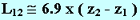
then the total length of stilling basin will be:

with X's value so as calculated above, for simple weir.
When a counterweir is being realised, the energy dissipation downstream the structure should always be quantified and, if necessary, reduced in order to prevent the scour phenomenon in the streambed. To quantify energy dissipation, the computation of the hydraulic flow conditions downstream the counterweir is necessary. The flow equation in Manning's formulation can be used to compute water depth and velocity within the stream reach:
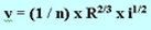
and

whereby:
n: Manning's coeffcient,
R: hydraulic radius,
i: streambed slope,
W: cross sectional area,
Q: discharge flow.
To avail oneself of these relations, different water depth values should be tried until the correct discharge flow value is identified.
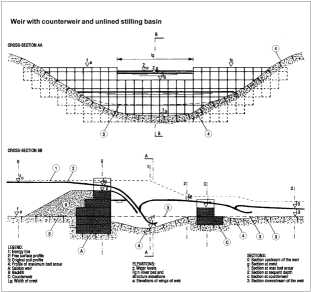
Fig. 3.17 - Weir with counterweir and unlined stilling basin
Weir with counterweir and lined stilling basin
If the streambed material is not very good (e.g. small grain sizes), the stilling basin will have to be lined in order to limit the weir's foundation level. For lining the basin's bottom a layer of gabions could be used, as shown in figure 3.18.
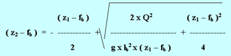
All the gabions structure's dimensions and water levels can be computed using flow-water's depth relations with the proper simplifying hypotheses. With reference to figure 3.18, the water depth of the supercritical flow is given by:
For energy dissipation to take place in the stilling basin, it should be seen that the hydraulic jump takes place. The water's depth of the subcritical flow is given by:
for obtaining this water depth, it will be expedient to realise a counterweir, the height of which can be computed through the usual depth-flow relationship:

To complete our knowledge of water levels, the water depth in non-aerated zones can be obtained from the following relation:

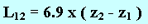
Before we can determine the stilling basin's length, we will have to calculate the distance from the weir at which the supercritical flow is installed and the length of the hydraulic jump. The former can be calculated as follows:
and the hydraulic jump length is given by:
At this point, we must verify that the stilling basin's flow behaviour is independent from the flow behaviour of the downstream reach. This will be confirmed if the total energy downstream is lower than on the counterweir.
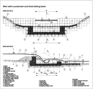
Fig. 3.18 - Weir with counterweir and lined stilling basin
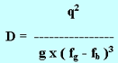
When the upstream side of the weir is completely filled with sediment, existing sample relations allow us to determine all the characteristics of the stilling basin with reference to the drop number (D). These relations have been obtained by means of experimental observations. The drop number is expressed by:
Once the drop number is known, all the characteristics of a weir with stilling basin can be obtained by applying the following relations:
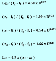
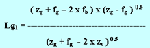
Sometimes, in order to reduce the quantity of gabions required for lining the stilling basin, it will be useful to place gabions lining only in the zone close to weir toe. The remaining portion of stilling basin will be lined with large stones (see figure 1.2). In this case, gabions lining has to extend itself up to a distance from the weir toe greater than Lg1, to protect this portion of the stilling basing, which is threatened by water falling from the weir crest.
Weir with counterweir and lined stilling basin located below the natural river bed
In this case, the basin's functioning is influenced by the subcritical flow downstream. To obtain all the characteristics of the stilling basin, the composite system shown below must be solved.
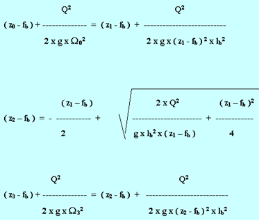
Some of the flow and weir characteristics needed to solve the system are already known. The values of z1, z2 and fb are the only unknown terms. It will be useful to preventively fix a value for fb, in order to compute the value of z1 in the first equation and the value of z2 in the second one. If, at this point, the third equation is not satisfied, it will be necessary to restart the calculations with another value for fb.
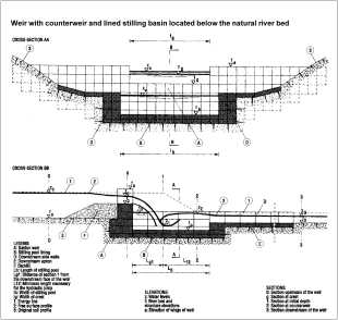
Fig. 3.19 - Weir with counterweir and lined stilling basin located below the natural river bed
Stepped weirs
This kind of weir is generally used in relation to low specific flows and significant drop heights. Experimental observations, conducted by Cemagref, show that stepped weirs are particularly convenient for specific flows inferior to 3 m3/m/s. For higher values of the specific flow, the gabions step could be damaged. In stepped weirs, the energy dissipation takes place already on the steps. In fact, the experimental evidence shows a 10%-30% diminution of the length of the stilling basin compared to the length obtained using traditional methods (Peyras , Royet , Degoutte. 1991).
With reference to a weir's specific flow and downstream side slope, four different kinds of hydraulic situations can take place:
-nappe flow, with flow alternatively in subcritical and supercritical range,
-nappe flow, with flow always in supercritical range,
-partial nappe flow, with flow always in supercritical range,
-skimming flow.
Battered weirs
This kind of weirs is generally well suited to significant drop heights and low specific flows (inferior to 1 m3/m/s). The specific flow has to be limited only if the weirs are built with gabions, which can easily be damaged. In fact, violent water flows can provoke stones' rubbing within gabions baskets, consequently leading to stone or net breakage. Transported materials colliding with gabions can also provoke net tear.
Battered weirs will require a reinforced concrete lining if the specific flow is higher than 1 m3/m/s. A detailed explanation of the methods used to dimension the stilling basin in the case of battered weirs can be found in U.S. Bureau of Reclamation 1987.
Verification against piping failure
In presence of a weir, the water level builds up bringing about a difference in level between the upstream and downstream side of the weir. The gradient thus established gives rise to a seepage reticule underneath the structure. The seepage's characteristics largely depend on the soil's materials. Given that gabions structures are generally built on pervious soils, the seepage phenomenon can provoke the formation of springs downstream the structure. A substantial spring flow can transport particles of soil material, progressively increasing water seepage and the amount of material transported, eventually leading to the structure's failure.
To test the weir against the possibility of a piping failure, the seepage reticule has to be determined. This will allow us to identify the seepage flow path and hydraulic gradient in the area underneath the structure (see figure 3.20). In order to determine the flow path and the hydraulic gradient of the seepage reticule, we will have to solve a composite system of differential equations. However, for the small structures dealt with in this work, the test against seepage can be generally accomplished using the Bligh method (U.S. Department of the Interior Bureau of Reclamation. 1987, Maccaferri 1990a ). According to this method, the structure will be tested against seepage when the following relation is verified:

whereby:
-L seepage path below the structure (the length of vertical is tripled in the sum),
-c coefficient depending on soil characteristics (see figure 3. for its values),
-Dh water level difference between upstream and downstream the weir.
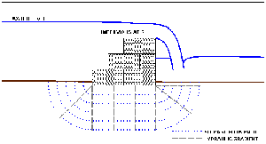
Fig. 3.20 - Seepage reticule below a weir
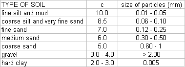
Fig. 3.21 - Bligh coefficient (c) values
If the above mentioned relation is not verified, then the weir section will have to be modified. A lengthening of the seepage path can be achieved in two ways (see figure 3.22):
-build a gabions' apron downstream the weir (case A)
-build an impervious cut-off below the structure (case B)
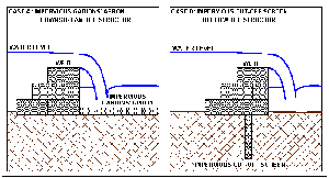
Fig. 3.22 - Methods for lengthening seepage paths (case A and B)
The actual seepage reticule will correspond to the one designed in figure 3.20 only in the hypothesis of a completely impervious structure, otherwise the seepage reticule will be influenced by the high permeability of gabions, which attract the seepage, causing it to deviate its path, as shown in figure 3.23.
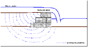
Fig. 3.23 - Seepage reticule in the hypothesis of pervious gabions
In this hypothesis, the probability that soil particles are transported by seepage is high. In fact, the soil in contact with gabions is exposed to water seepage pressure but, on the other hand, it is also influenced by atmospheric pressure or water pressure below the water level. However, water's seepage pressure is generally higher than the latter two, and it can remove fragments of material in contact with gabions. To eliminate this problem, a layer of graded material, such as gravel, should be interposed between gabions and soil. Also a layer of geotextile, generally easier to install, would suit the purpose. Another feasible solution consists in placing an impervious membrane between gabions and soil. Through these devices the weir is rendered completely impervious and Bligh's theory can be used for testing the weir against excessive seepage.
Whether graded material or geotextile is chosen, the layer will inevitably be obstructed by the particles transported by water's seepage and will consequently become impervious.
3.3.4 - Stability analysis
This paragraph illustrates the procedure used to test the stability of gabions structures (Maccaferri 1990a). First of all, it will be useful to introduce loads analysis, with regard to both horizontal thrusts and vertical loads on the structure. Then, four different stability tests for gabions structures will be explained, namely:
-against overturning,
-against sliding,
-against uplift,
-against excessive pressure on foundation soil.
With respect to figure 3.24, loads on the weir structure are explained below.
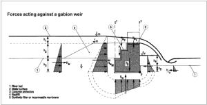
Fig. 3.24 - Weir cross-section for stability analysis
Horizontal thrusts
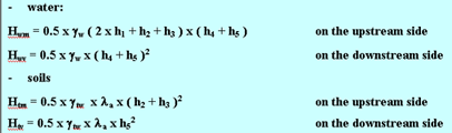
In these relations, symbols represent:
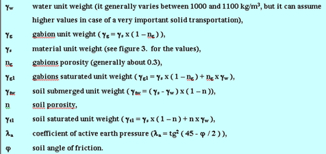
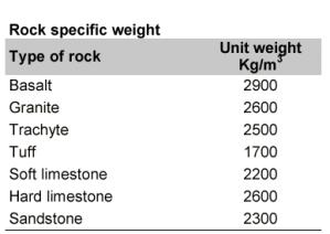
Fig. 3.25 - Soil unit weight
Test against overturning
The test must be conducted in relation to the structure's overturning around the F point (see figure 3.24 ). Below are detailed overturning and stabilising forces:
overturning forces
-horizontal thrusts by water ( Hwm , Hwv ),
-horizontal thrusts by soil ( Htm ),
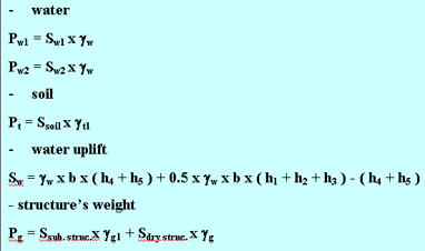
-water uplift ( Sw )
stabilising forces
-structure weight ( Pg ),
-water weight ( Pw1, Pw2 ),
-soil weight (Pt ),
-horizontal thrusts on the downstream side by water and soil (Hwv , Htv ).
Multiplying the forces for their respective arms and summing all the overturning and stabilising moments, we obtain the following relation, which shows the structure's stability coefficient:

where Ms is the sum of the stabilising moments and M r is the sum of overturning forces. For small structures sr > 1.3. For more important structures, instead, the stability coefficient against overturning will take up higher values.
Other tests against overturning are normally required at different structure levels, but the procedure illustrated above is generally the fundamental one, for the majority of structures.
Test against sliding
To carry out this test, horizontal ( S H ) and vertical ( S V ) forces' resultants must be calculated. The following relation has to be verified:

whereby j represents the friction angle between gabions and foundation soil. A common value for the friction angle j is 35° with a corresponding tg j @ 0.7. In this case, the stability coefficient against sliding will be expressed as:

As for the overturning, ss must be greater than 1.3 for small structures. For more important structures, the stability coefficient against sliding will take up higher values. suitable.
Verification against uplifting
Lining the stilling pool is usually necessary to protect against seepage failures. Where this lining is constructed using gabions or mattresses laying on a reverse filter or a geotextile, it is necessary to check the stability of the lining against hydraulic uplift, and check that the uplift force due to seepage water is not greater than the combined weight of the lining and of the interstitial water, filters, and the water passing over the lining. It is therefore necessary to evaluate the distribution of pressures under the stilling pool by drawing a flow diagram or by using the simplified method already suggested. With reference to figure 3.24, the pressure, p, at each point of the foundation is
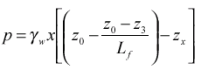
If h is the depth of the water above the apron and s the thickness of the apron, then the coefficient of stability against uplift is
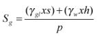
Acceptable values of safety factor S g are between 1.1 and 1.2.
Resistance test for the foundation soil
For each section under examination, all the forces H wM , H wV , H tM , H tV , P w1 , P w2 , t P, P g and S w of Figure 3.24 are computed for the worst case. The intensity and the trend of the resultant R of the acting forces, its inclination and the centre of gravity, are then determined. It is conservatively assumed that the gabion foundation surface remains flat and that the foundation soil is much less rigid than the gabion structure. With regard to this second assumption, the results of experiments indicate that the rigidity of gabions is comparable to that of soil.
If the centre of gravity of X is within the middle third MN the pressure is distributed over the whole foundation, and the maximum pressure,s B , at the downstream toe, B, in kg/cm 2 , is found from:
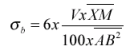
where: V is the vertical component of the resultant R (kg); and XM and AB are distances (cm).
If the centre of gravity is coincident with the extreme edge of the middle third (N), the maximum pressure, s B , is:
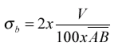
A centre of gravity outside the middle third - MN - is to be avoided, since, in accordance with the assumption made above, only part of the foundation is utilized. In practice this is an unlikely situation in a gabion structure due to its great flexibility, but in such a case, the pressure s B would be:
The maximum pressure s B should be lower than the foundation soil bearing capacity given for various soils in Fig. 3.26.
