3.2 - DISCHARGE CHANNEL OF THE SPILLWAY
Various kinds of problems could be avoided if the spillway's discharge channel is accurately designed. The channel's principal characteristics are:
-transversal section and longitudinal slope both apt to evacuate the design flow,
-lining to prevent bank and bed erosion caused from water flowing,
-protection of the bank (side slope and gutters).
The dimensions of the transversal channel section and the longitudinal slope have to be calculated in accordance with the design flow in order to limit the water's speed. It is always preferable to opt for a large channel with a slight slope, rather than a narrow channel with a steep slope. Even if the first solution is somewhat more expensive to be realised, it normally proves cheaper later, because it requires a minimal upkeep with low related maintenance costs.
If the channel bed's soil materials cannot support the water flow, the channel will have to be lined with more resistant materials. In this case, the channel bank should be protected with a small gabions retaining wall. Gutters must be built to prevent channel bank erosion caused by the runoff coming from upstream the hill in which the channel is built (see figure 3.2).
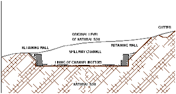
Fig. 3.2 - Cross section of spillway channel
3.2.1 - Hydraulic design
The spillway should be commensurate to the design flow. As mentioned above, the spillway is generally composed by a discharge channel and by a drop system: both these components have to be dimensioned according to the design flow. The dimensioning of a drop system will be explained in the following paragraph (3.3). Here the stream-flow computation for designing the discharge channel will be briefly explained (U.S. Department of the Interior Bureau of Reclamation. 1987).
In an open channel, in which, by hypothesis, flow streamlines are parallel and the speeds of all the points in a cross section are equal to the mean velocity v, water's energy consists of two components: kinetic and potential (Bedient P., Huber W. 1987). With reference to figure 3.3, the absolute head of an open channel's flow discharge is expressed by Bernoulli's equation:

whereby:
z: channel bottom level,
d: water depth,
v: mean velocity,
g: gravity acceleration.
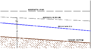
Fig. 3.3 - Flow in a channel
The energy at the channel's bottom, named 'specific energy', is represented by the relation:

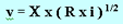
the velocity v in a open channel can be expressed by:

whereby:
Q: discharge (volume rate of flow),
W: cross sectional area of flow,
then, the specific energy can also be expressed as

It is crucial to understand this formula correctly. The relation can be plotted with respect to the specific energy ( He ) and the water depth ( d ) axes (see figure 3.4), for different discharge ( Q ) values. The diagram shows that, for fixed discharge values Qf and specific energy Hf, there are two possible depths d1 and d2, where d1 is related to a sub-critical flow and d2 to a super-critical flow.
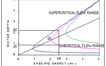
Fig. 3.4 - Flow's depth-energy relationship in the channel

with
It can be seen that in the supercritical flow range, the water velocity is always higher than in the subcritical flow range. There is also a minimal specific energy ( Hm ), to which corresponds a unique value of water depth ( dm ). When this condition occurs, the flow is named critical, as well as all the other characteristics (i.e. depth, velocity and slope).
The key parameter used to express the discharge flow condition is the Froude number:
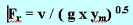
whereby ym is the average flow depth. If
Fr > 1, then the discharge flow is in supercritical conditions,
Fr < 1, then the discharge flow is in sub-critical conditions.
Establishing whether a flow falls in the supercritical or the subcritical range is very important. Firstly because, in small hydraulic works, all the structures should be designed, if possible, so as to keep the flow in the subcritical range. In fact, problems caused by water's erosion are reduced at the subcritical range's lower flow speed.
Figure 3.5 shows what happens when a discharge flows in the spillway channel of an impoundment. At the channel's entrance, there is a transitional zone to which corresponds a loss of specific energy due to entrance frictions. Simultaneously, the water starts flowing in the channel and the energy passes from potential to kinetic. In the impoundment, the kinetic component of specific energy is generally negligible and the specific energy line corresponds to the water level.
After the transitional zone, the discharge flow is in a uniform condition, with the water level parallel to the channel bottom. In this zone, it is always preferable to keep the flow at a subcritical level, to avoid scour problems in the channel. Otherwise, it will be necessary to line the channel with reinforced concrete. Close to the final drop, at the end of the channel, the flow's speed rises and the water level decreases until it reaches the critical condition on the drop. The following paragraph illustrates what happens beyond the drop.
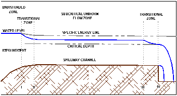
Fig. 3.5 - Schematisation of a spillway channel
The design of a spillway channel should aim at minimising specific energy losses and at limiting the water's speed to prevent scour problems. Minimising specific energy losses will allow us to design a higher channel bottom, thus reducing the amount of earthworks. Reducing water erosion will allow us to shield the channel bed with a simple and superficial lining (e.g. with a thin layer of rubble and stones). If the natural soil is of a resistant quality, channel lining will not be necessary. In order to minimise energy losses at the channel entrance, a progressively straitening, funnel-shaped entrance should be substituted to the natural entrance. If the new funnel-shaped entrance is properly realised, specific energy losses will amount to a few centimetres only.
Where a uniform flow is achieved, after the transitional zone, the usual flow-depth relationship can be used for calculating the water depth corresponding to the design flow. For this computation, the channel bottom's slope and its roughness in relation to the materials lining the channel should be fixed in advance. One of the relationships used most frequently for flow computations in open channels is Manning's formula (Bedient P., Huber W. 1987, FAO. 1996 , Maccaferri 1990a):

which derives from Chezy's general formulation:
whereby:
n: Manning's coefficient,
k: Gaukler-Strikler's coefficient,
R: hydraulic radius,
i: spillway channel longitudinal slope,
C: Chezy's coefficient.
The best way to use Manning's relationship is to make repeated attempts with different water level values in order to compute the flow's velocity and, consequently, the flow's discharge, using the relation

until, in the spillway channel, the water level that allows the passage of the design flow is eventually found. The values of Manning's (n) and Gaukler-Strickler's (k) coefficients are tabulated relatively to the channel bottom and bank materials (see figure 3.6).
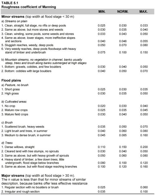
Fig. 3.6 - Coefficient values for flow relations in open channels
When the value of the water level required to evacuate the design flow in the spillway channel has been established, a verification of water levels in the channel entrance is necessary. With respect to figure 3.5 , the sum of absolute head and energy losses in section II must be inferior to the absolute head in section I, otherwise the discharge rate in the channel will be lower than the design flow.
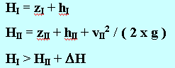
DH is negligible if the channel entrance is well realised. If this relation is not verified, then the spillway channel's characteristics should be modified (i.e. augmentation of width or slope, modification of channel lining in order to diminish its roughness).
If the compatibility of absolute heads expressed in the above relation is satisfied, then the channel bed's resistance to scour must be verified. The maximum flow speed values that do not provoke erosion are tabulated in figure 3.7 for several materials.
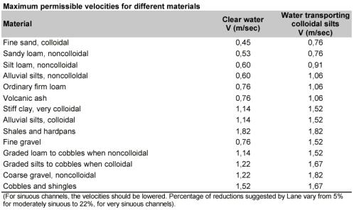
Fig. 3.7 : Maximum water speed tolerated by different materials
These values have been extrapolated from different theories (e.g. Shields' diagram, which imposes a fixed value for the critical shear stress), with the support of experimental observations ( U.S. Department of the Interior Bureau of Reclamation. 1987 Maccaferri 1990a). If the calculated water speed in the spillway channel is higher than the maximum tolerable speed for the bottom material, taken from figure 3.7, then the spillway channel's design should be modified. Two are the possibilities:
-augmentation of channel width and/or diminution of channel slope in order to lower the water speed,
-channel lining with proper materials which resist to the calculated water velocity.
After having modified the spillway channel's characteristics in one of the two possible ways that have just been mentioned, a new test to ascertain that the water speed is inferior to the maximum speed tolerable by the channel bed's material is necessary. Then, the verification expression, with new absolute heads' values, will have to be reformulated because the channel's hydraulic characteristics have now changed.
When the spillway channel is very short, its realisation in reverse slope is generally preferable, especially if the natural soil materials are not particularly resistant to water flow. With a reverse slope, the water speed in the channel is lower than in the vicinity of the final weir and the risks of channel erosion are reduced. Moreover, the reverse slope also prevents water stagnation in the discharge channel. Especially in arid and semi-arid regions, water stagnation facilitates the growth of vegetation, introducing new maintenance requirements.
3.2.2 - Protection of channel sides and bottom
Shields' diagram allows us to calculate the minimal size at which particles are not transported by water flow in the channel. If the natural soil material contains a percentage of particles of a size smaller than that calculated through Shields' diagram, the water flow can give rise to an important scour phenomenon in the channel. In this case, the channel bed will have to be lined with a more resistant material, e.g. containing a higher percentage of gravel, rubble and stone, and a small percentage of sand and clay. This material must be properly graded in order to obtain a high percentage of particles (between 80 and 90 %) with a diameter larger than the one computed with Shields' diagram. Some lines of gabions transversal to the channel can be inserted to prevent bed scour. The gabions' level should be positioned a few centimetres above the channel bed's lining, as shown in fig. 3.8.
In humid zones a turfing protection can be used for lining the spillway channel.
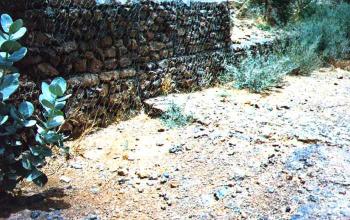
Fig. 3.8 - Linear protection of gabions on the channel bottom
If the channel crosses layers of material particularly vulnerable to water erosion, the spillway channel sides should be protected with retaining gabion walls to prevent banks erosion. The retaining walls at the sides of the spillway channel will also serve the purpose of stabilising the channel bank slopes made of incoherent materials.
The retaining walls cross section must be calculated according to earthfill and water stresses. The procedures for verifying the stability of the retaining walls are similar to the ones used to verify weir stability, which will be explained in the following paragraph (3.3).
Figure 3.9 shows two possible ways to realise the cross section of retaining walls. Option A is to be preferred if banks are made of rather resistant materials and the earthfill is properly compacted. In all other cases, option B will be more convenient.
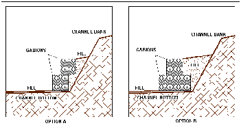
Fig. 3.9 - Retaining walls (options A and B)
Gabions retaining walls establish a preferential flow path, especially in the areas close to the bottom and the sides of gabions. In these areas, the internal conformation of gabions, with rubbles and channels, can cause the acceleration of the water flow. The erosive potential of water is increased, and the finest particles of material in contact with the gabion can be removed. This erosion phenomenon, peculiar to the areas in the vicinity of gabions, causes settlements of the wall, eventually leading to its failure. The most effective techniques to prevent erosion problems will be mentioned here very briefly. A detailed illustration of these techniques, and of the procedures to follow for their realisation, can be found in chapter VII.
The problem of erosion in the contact zones between gabions and natural soils or artificial earthfill embankment is common to all the hydraulic structures that include gabions (i.e. retaining walls, weirs, counter-weirs). To limit this problem, it is possible to resort to several solutions, two of which are particularly effective:
-interposition of geotextile between gabions and natural soil or artificial earthfill,
-building of semi-permeable or impervious cut-offs.
The first solution is the most suitable one. In fact, a geotextile layer should always be placed at the interface between gabions and natural soil or artificial earthfill, when the gabions structure can be interested by water passage. If the passage of water throughout the gabion structure is critical, then it is preferable to build semi-permeable or impervious cut-offs. These cut-offs should be built transversal to the flow direction to reduce water's erosive power. Semi-permeable cut-offs are realised interposing a geotextile layer between two layers of gabions. Impervious cut-offs, instead, take the form of a concrete wall, or walled gabions (gabions realised with a particular technique).
Above the banks of the spillway channel, a gutter should be installed to drain and to evacuate runoff water coming from upstream the channel, which, left unchecked, could lead to bank erosion (see figure 3.2).